General
Settings
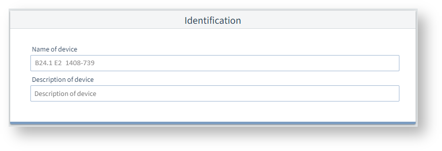
Identification
Device name
To uniquely identify a device, enter a name (max. 127 characters). The name is displayed in the header of the device display and in the GridVis® software.
Device description
Free text field for a more detailed description of the device function, location, etc. (max. 229 characters). The description is stored in the database and only displayed in the GridVis® software.
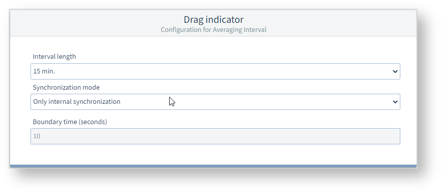
Drag indicator
The drag indicator function records the 3 highest average values over a defined period (time base). The measurement device determines drag indicators for currents, active and apparent powers.
Time base
The measurement device calculates the average values from the measured values over this period. The 3 highest average values are saved with a time stamp.
Synchronization mode
The synchronization determines the start time for the time base.
You can optionally start the synchronization via:
The internal device clock (setting Internal synchronization only).
A parameter setting (setting Synchronization via Modbus).
For internal synchronization, the option Synchronization via Modbus must be deactivated!
Capture time (seconds)
The Capture time describes the time window in which an incoming pulse synchronizes the time instant.
If the device receives a pulse outside the capture time, the calculated average values are deleted and the time is reset.
Note
The value set under Capture time describes half the time window of the total capture time (see user manual).
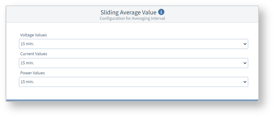
Sliding Average Value
The measurement device records average values for the measured voltages, currents and powers including a time stamp.
Moving or sliding averages always apply to the last elapsed time interval, starting from the current time. The average values are recalculated every minute.
Example: Setting 15 min
When the values are queried at 10:18, the average values for the interval 10:03 to 10:18 are sent (accurate to the second for the last 900 s).
Voltage values
Time interval for capturing the average voltage values.
Current values
Time interval for capturing the average current values.
Power values
Time interval for capturing the average power values.
Note
The time intervals defined here are used not only for the moving averages, but also in other contexts when the average (or minimum/maximum value) can be selected in a field. When a voltage, current or power is selected, the associated interval is used.
The intervals of the moving average are taken into account, for example, on the following configuration cards:
Logic > Comparator
Further notes:
The average values and the associated 200 ms minimum and maximum values can be read out via Modbus addresses.
The meter overwrites the Modbus addresses with the average values and the associated minimum and maximum values for each interval, even if the previous values were not retrieved.
In addition to the measured values, the time stamp is also provided in Modbus addresses. More information on this can be found in the user manual and the Modbus address list available for download at www.janitza.de.
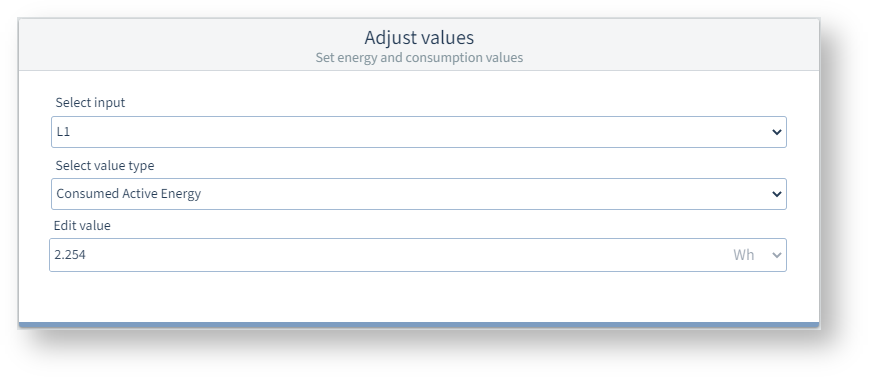
Setting values
When you replace a measurement device with a new one, you can set the last values of the old measurement device as the start values for the new measurement device here.
To set consumption values:
Read out the previous values that are to be used as the new start values.
Fill the Select input, Select value type and Edit value fields with a starting value.
Repeat step 2 for all desired inputs (start values).
Transfer the configuration to the device to set the Start values.
Select input
Select value type
In these fields, select a measured value for which you want to set a start value.
Edit value
Specify the start value to be transferred to the measurement device for the measured value selected under Select input and Select value type.
By default, this field displays the current meter reading in the measurement device. Consequently, the meter reading in the measurement device will not be increased when you retransmit the configuration to the measurement device .