Integrating a Non-Proprietary Device into the GridVis software
KBR multicomp
KBR multimess Basic
Siemens Sentron PAC3100
Schneider Power Logic PM800
Schneider Power Logic PM5561
TIP NOVA 5//1 A MID-4L, Three-phase transformer counter
You can integrate a non-proprietary device through the generic Modbus into the GridVis software as follows:
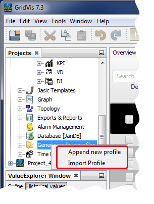
After you have opened the window Projects, right-click on the directory entry Generic Modbus Profile.
The context menu will open.
In the context menu, click on the entry Create New Profile.
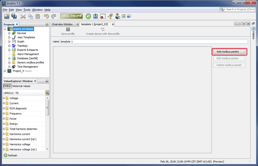
The window Template will open.
Click on the button Add Modbus Package to add a data package to the generic Modbus profile.
The window Configure Modbus Value List will open.
|
Pos. |
Description |
|
1 |
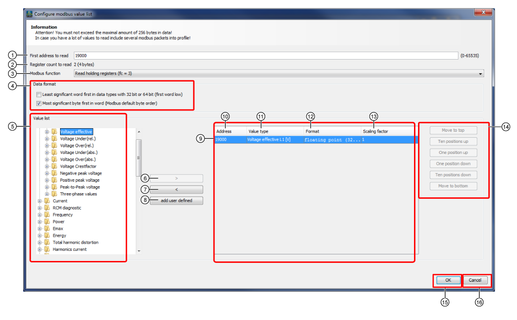
Search in the Modbus address list of your device (non-proprietary device) for the corresponding measurement values. Enter the Modbus address assigned to the measurement value into the entry field First address to be read. Note Measurement values and their Modbus addresses are recorded in the GridVis software in Modbus packages (data blocks). The contents and the order of the Modbus addresses can be found in the device manufacturer’s data sheet (Modbus profile setup). Please note the setting Format (see Pos. 12). For Modbus addresses that do not correspond with the order, use the button Add Modbus Package to create a new Modbus package in the Template window (see above, fig.: Window Template - Button Add Modbus Package). You can add missing measurement values in the value list by using the button User-Defined Value (Pos. 8). |
|
2 |
Register number and size of the address entry. |
|
3 |
Note Please note the appropriate information in your device's Modbus address list (e.g. the Modbus functions as a master or slave device) to set the Modbus function. Selectable Modbis functions:
|
|
4 |
In Value Format, select the byte order of your data type:
|
|
5 |
Measurement values supplied by the GridVis software that should be read out with Modbus. You can add missing measurement values in the value list by using the button User-Defined Value (Pos.8). |
|
6 |
Adds a measurement value to the display Recorded Measurement Values (Pos.9). |
|
7 |
Removes a measurement value from the display Recorded Measurement Values (Pos.9). |
|
8 |
Creates user-defined measurement values through a dialog (name and unit of the measurement value) that are recorded in the display Recorded Measurement Values (Modbus-Paket). |
|
9 |
Display of recorded measurement values (in Modbus packages), that should be read out through Modbus by the measuring device (non-proprietary device). Measurement Value - Details: Address, value type, format and scaling factor. For this, you will require the data sheet (Modbus profile setup) from the device manufacturer. Display in Modbus packages (data blocks). Note You can create new Modbus packages for the different data blocks (non-consecutive measurement values in the data sheet of the device manufacturer) (cf. Add Modbus Package). |
|
10 |
Address of the measurement value assigned from the Modbus address list (device manufacturer data sheet). Depends on the selected format (data type) of the measurement value. |
|
11 |
Measurement value of the device (non-proprietary device) recorded by Modbus. |
|
12 |
The Format to be set up, also called data type, can be found in the data sheet (Modbus profile setup) from the device manufacturer.
Standardized data types: Expanded data types: |
|
13 |
The scaling factor describes the resolution of the measurement value in the graphical display. |
|
14 |
Click on the corresponding button to position your measurement value in the display Recorded Measurement Values.
|
|
15 |
Saves the configured value list. |
|
16 |
Deletes the configured value list. |
After you have set up the Modbus packages, click on the button OK to open the window Template (Further figures of examples follow. The depictions do not correspond with real configurations and serve only to explain).
|
Pos. |
Description |
|
1 |
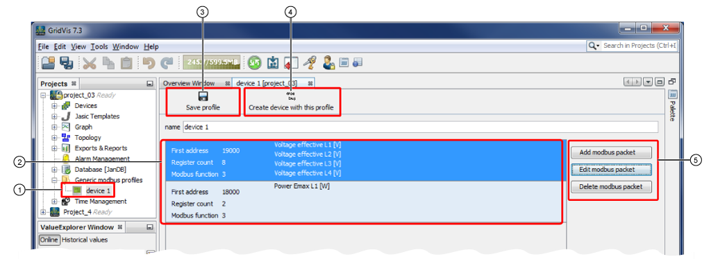
Generic Modbus profile saved in the project with the Modbus packages that were created. |
|
2 |
List of all the Modbus packages already created in the Modbus profile. |
|
3 |
Saves the Modbus packages you created in the generic Modbus profile. |
|
4 |
Creates a new device with the generic Modbus profile that was created (cf. next step). |
|
5 |
Opens the configuration window for a new Modbus package. Opens the configuration window of an existing Modbus package. Deletes the selected Modbus package. |
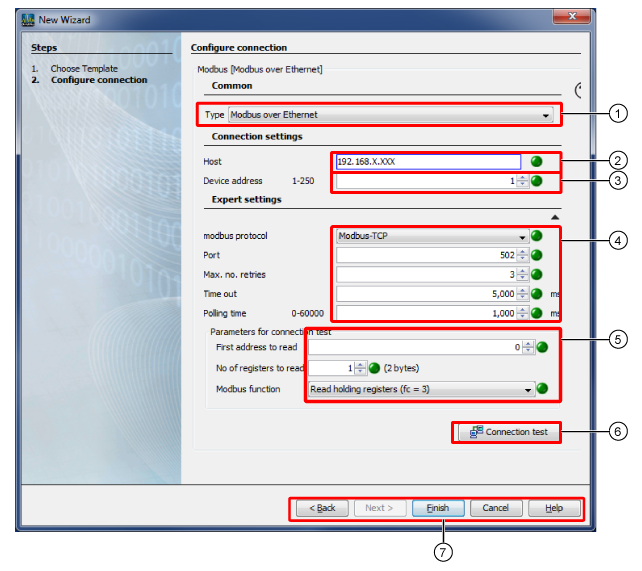
Required parameters for the connection type Modbus via Ethernet:
|
Pos. |
Description |
|
General settings |
|
|
1 |
Option list Connection Type For non-proprietary devices that serve as a placeholders for offline configurations. To connect a serial interface for non-proprietary devices via the interface Modbus RTU (RS485/RS232), (cf. following step Configure Connection - Modbus RTU (RS485/RS232)). To connect an interface for non-proprietary devices via Modbus Ethernet. |
|
Connection settings |
|
|
2 |
Select the Host/IP Address of the master device (master gateway). |
|
3 |
Select the Device Address of your measuring device (non-proprietary device). Note When setting the Device Address, please observe the master/slave principle of your device architecture! Here, a Janitza UMG can serve as a master gateway device just as well as e.g. a non-proprietary device. |
|
Expert settings |
|
|
4 |
In the Modbus protocol, select Modbus-TCP. The TCP port 502 is reserved for the Modbus-TCP. Number of attempts for the connection test. Time setting used to determine whether data packages have been lost in the network. Time (in ms) in which a confirmation of receipt (Acknowledgment Flags) for a TCP data package arrives from the opposite site at the sender. Query cycle (in ms) in which the data packages are queried. |
|
5 |
The data sheet (Modbus profile setup) from the device manufacturer (non-proprietary device) is needed for these settings. Cf. window Configure Modbus Value List. First Address to be Read Select the Modbus profile setup. Select the number of registers (the size of the address entry appears in brackets). Select Modbus function - Standard setting"Read holding registers (fc = 3), e.g. for reading out measurement values, counter states and the device configuration. |
|
6 |
If the connection test is negative, the window Device Information will open with details on:
If the connection test is negative, the window Connection Test Failed will open:
|
|
7 |
Buttons: Leads to the first step of the dialog, Select Template. Is active to get from step 1, Select Template, to the second step,Configure Connection. Creates a device with the assigned profile. Deletes the entries in the window Configure Connection Opens the direct help guide. |
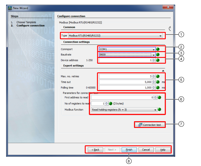
Required parameters for the connection type Modbus RTU (RS485/RS232):
|
Pos. |
Description |
|
General settings |
|
|
1 |
Option list Connection Type For non-proprietary devices that serve as a placeholders for offline configurations. To connect a serial interface for non-proprietary devices via the interface Modbus RTU (RS485/RS232), (cf. following step Configure Connection - Modbus RTU (RS485/RS232)). To connect an interface for non-proprietary devices via Modbus Ethernet. |
|
Connection settings |
|
|
2 |
Select serial interface (COM port). Note When setting the Interface please observe the master/slave principle of your device architecture! |
|
3 |
Select baud rate. Select a uniform baud rate within one bus structure (master/slave principle)! |
|
4 |
Select the Device Address of your measuring device (non-proprietary device). |
|
Expert settings |
|
|
5 |
Number of attempts for the connection test. Time setting used to determine whether data packages have been lost in the network. Time (in ms) in which a confirmation of receipt (Acknowledgment Flags) for a TCP data package arrives from the opposite site at the sender. Query cycle (in ms) in which the data packages are queried. |
|
6 |
The data sheet (Modbus profile setup) from the device manufacturer (non-proprietary device) is needed for these settings. Cf. window Configure Modbus Value List. Select First Address to be Read from your Modbus profile setup. Select the number of registers (the size of the address entry appears in brackets). Select Modbus function - Standard setting Read holding registers (fc = 3), e.g. for reading out measurement values, counter states and the device configuration. |
|
7 |
If the connection test is negative, the window Device Information will open with details on:
If the connection test is negative, the window Connection Test Failed will open:
|
|
8 |
Leads to the first step of the dialog Select Template. Is active to get from step 1, Select Template, to the second step,Configure Connection. Creates a device with the assigned profile. Deletes the entries in the window Configure Connection. Opens the direct help guide. |