RCM 202-AB
|
Bereich |
Beschreibung |
|
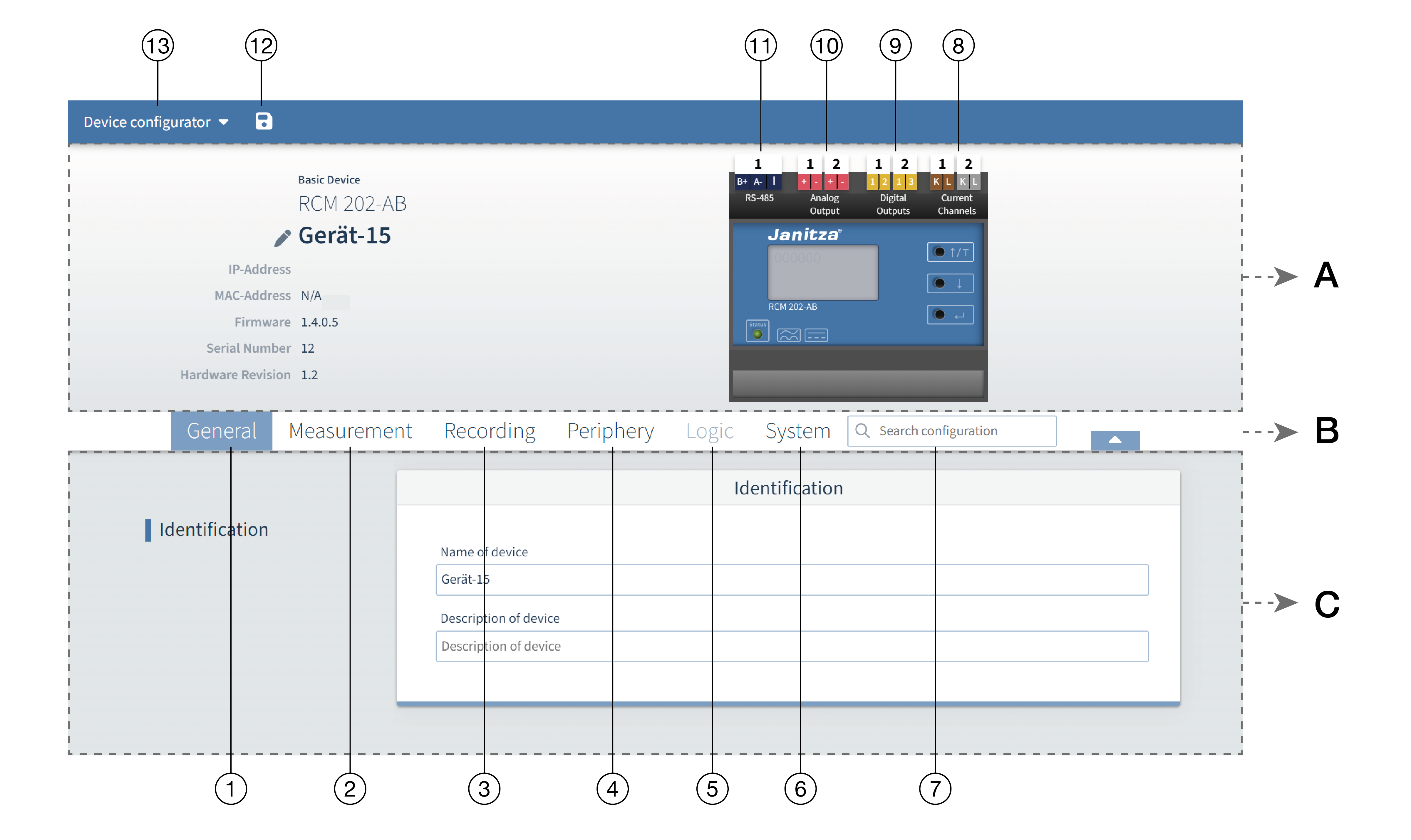
A - Info & Configuration |
In this section you will find basic information about the device, as well as an overview of the device and its connections. Clicking on the corresponding connections opens a configuration window for the selected connection/channel and the corresponding configuration card in the lower area. |
|
B - Menu bar |
You can quickly navigate to the desired configuration card using the tabs for the corresponding main categories and the search field. |
|
Configuration |
In the lower area you will see all available tabs depending on the active channel/connection or the selected tab. |
There are two possibilities for the device configuration:
Selecting the tabs in the menu bar (area B) opens the corresponding higher-level category and selects the configuration card.
Click directly on the connecting element in the schematic image to navigate to the desired configuration card (example: to configure digital output 1, click directly on the number "1" with the white background above the "Digital outputs" label) (see Overview under point 9)
 Note: Click directly on a connection in the schematic image to obtain additional information on the selected element.
Exemplary quick guide for a possible configuration
This is an example, the steps may vary depending on the configuration example.
Configuration steps:
Assign a device name (see table item 1)
Set the current transformer type (see table item 2)
Configure the residual current measurements (see table item 2)
Set the averaging time of the recording (see table, item 3)
Set the digital outputs (see table item 4)
Set the analog outputs (see table item 4)
Synchronize the device time (see table item 6)
Adjust the communication settings (RS-485) to the actual network environment (see table item 6)
Select a test interval to configure the RCM test functions (see table item 6)
"Device configurator" menu
|
Pos. |
Name |
|
Description |
|
|
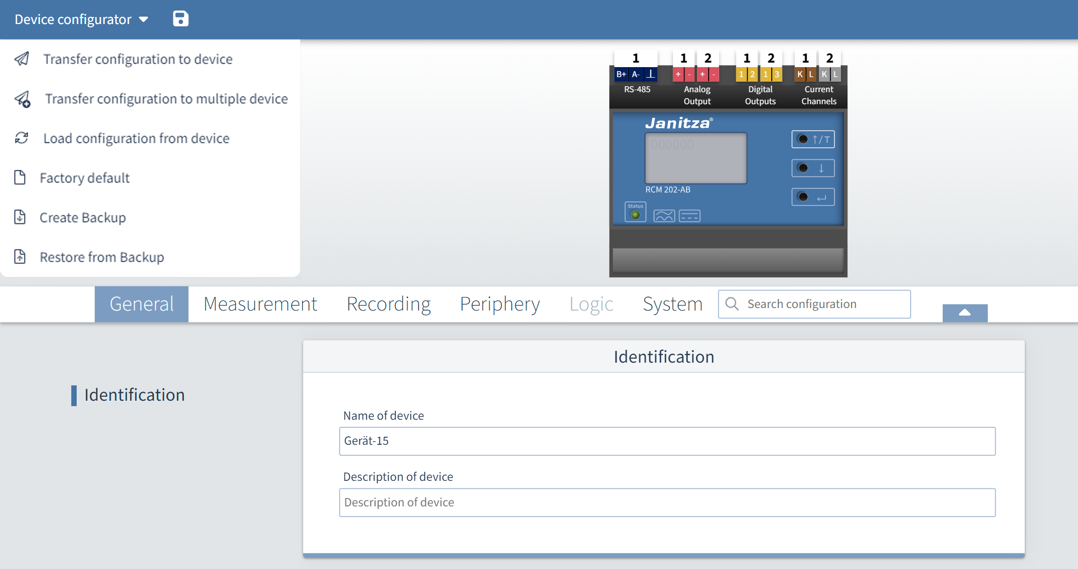
1 |
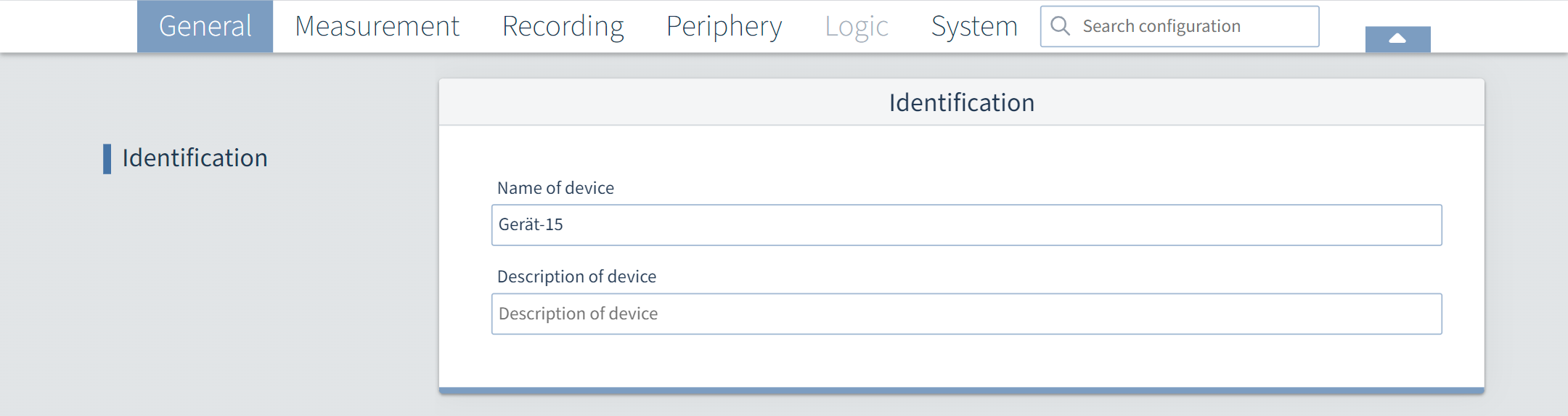
General |
Identification |
Name of the device: Enter the freely selectable device name (max. 255 characters). Description of the device: If desired, enter a freely selectable description of the device (max. 255 characters). |
|
|
2 |
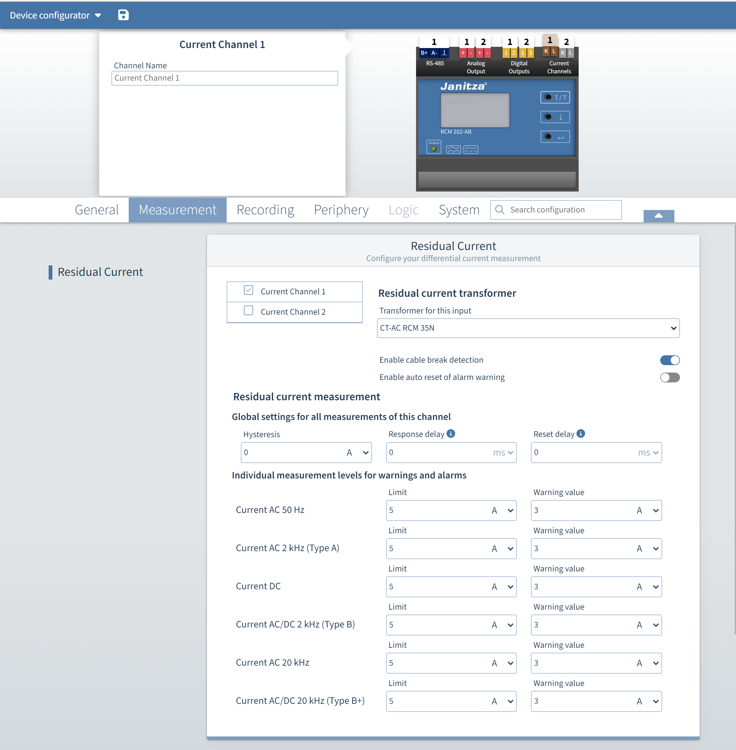
Measurement |
Residual current Click directly on the current channel in the device image, see Overview no. 8 |
Selection of the · Current channels |
|
|
|
Configuration of the current transformers and the associated residual current measurements
|
|||
|
3 |
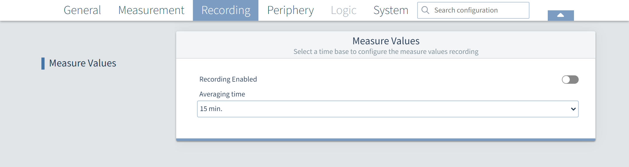
Recording |
|
You can activate recording and set the averaging time here. |
|
|
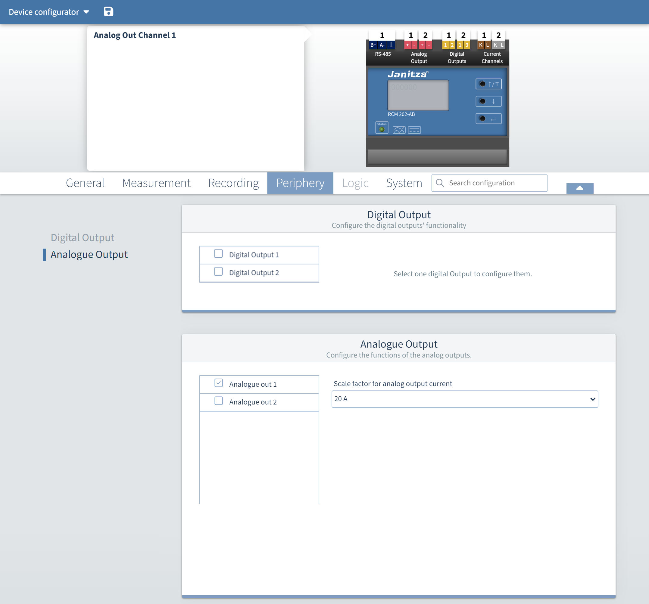
4 |
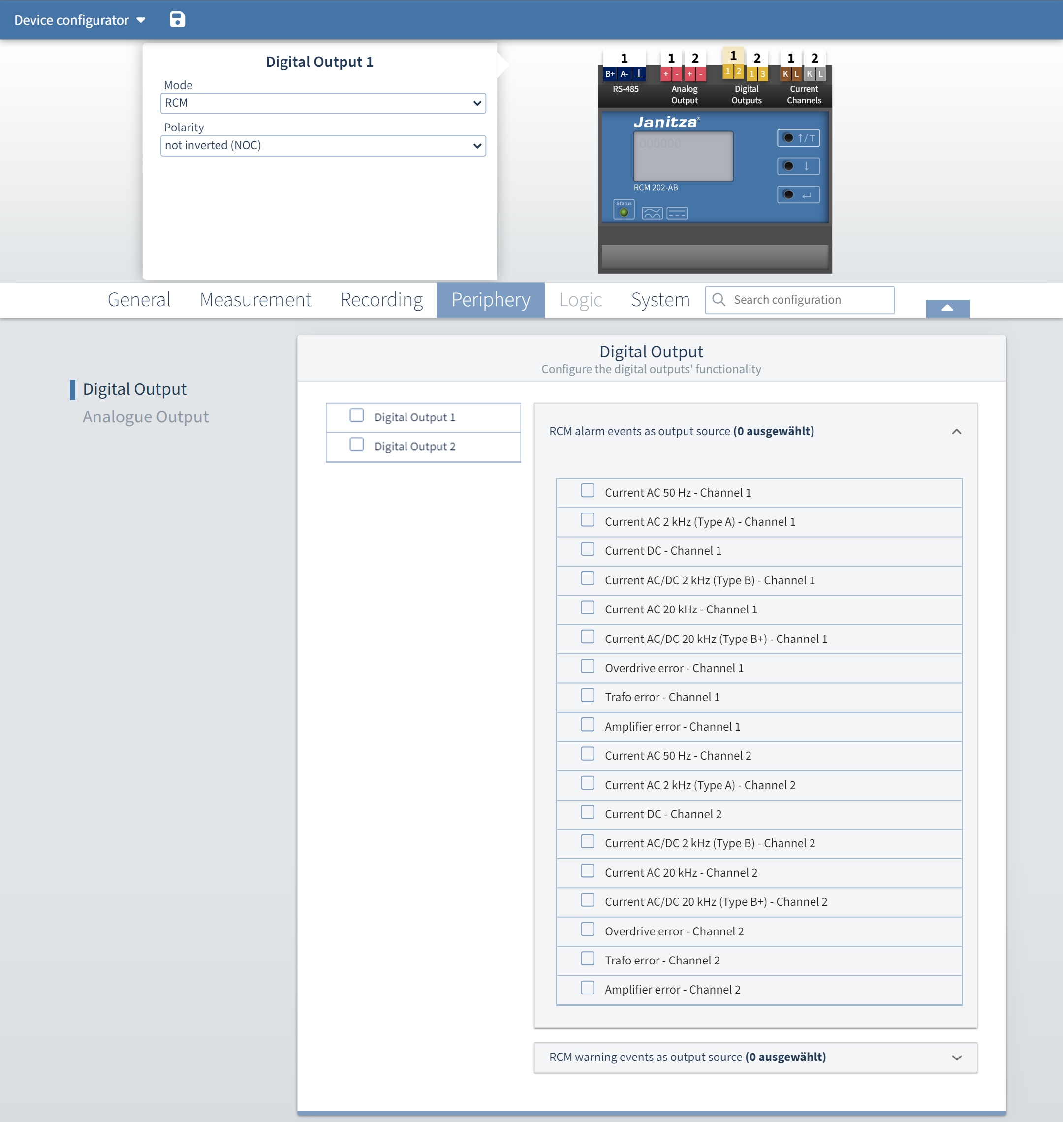
Peripherals |
Digital outputs Click directly on the digital output in the device image, see Overview no. 9 |
Here you can select the error and warning states for the two digital outputs (multiple selection possible). You can also set the polarity (normally open or normally closed contact). |
|
|
Analog outputs Click directly on the analog output in the device image, cf. overview no. 10 |
Here you can set the scaling range of the output current for the two analog outputs. |
|
||
|
5 |
Logic |
|
Not yet available at this time |
|
|
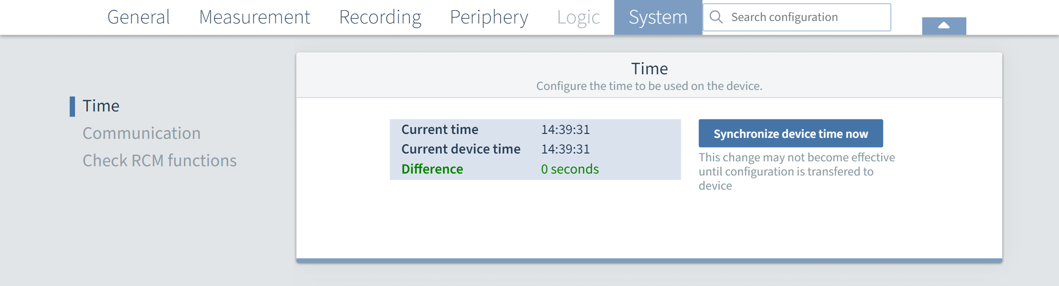
6 |
System |
Time |
Synchronize the
by selecting the button "Synchronize device time". This change will take effect when the configuration is transferred to the device. |
|
|
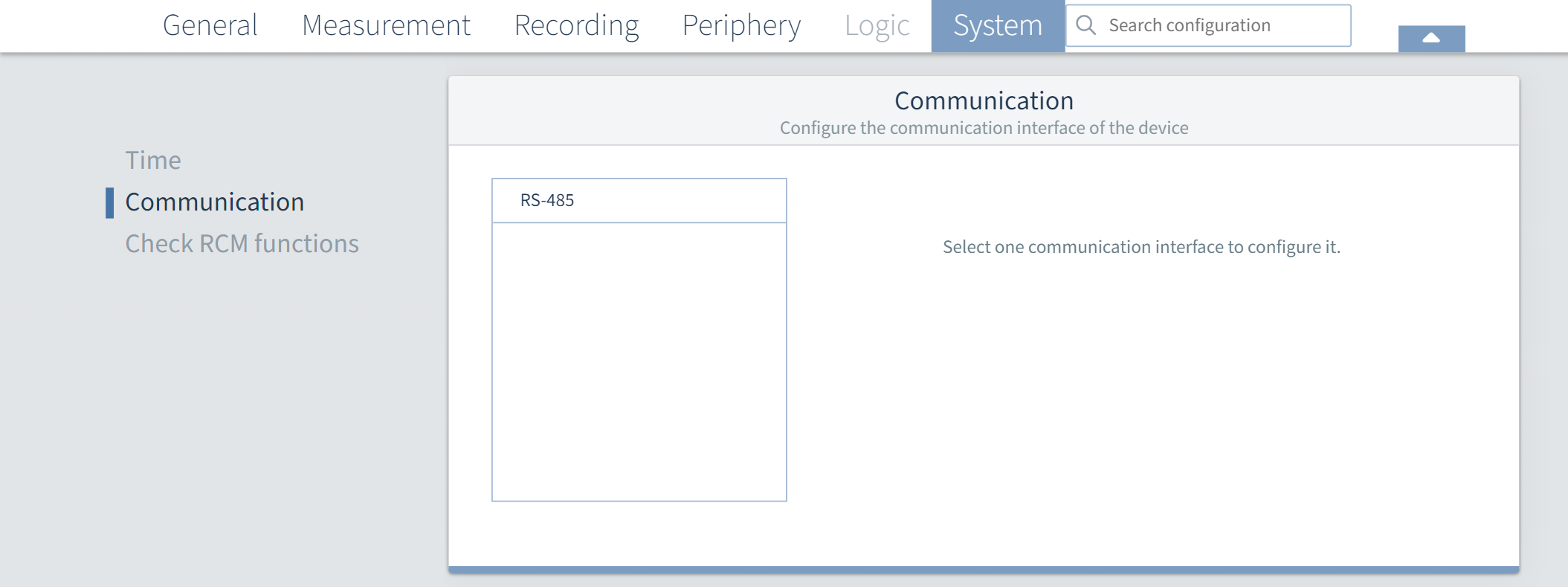
Communication |
Configure the RS-485 interface with the following parameters
The Modbus mode cannot be changed because the device can only be used as a slave.
|
|
||
|
Testing RCM functions |
Here you can set a test interval for the RCM test functions. Possible input: "No test interval...", 1 month, 3 months, 6 months and 12 months. |
|
||
|
7 |
Search configuration |
|
Enter a keyword and you will be taken directly to the corresponding configuration menu. |
|
|
8 |
Current channels |
|
See point 2 (Measurement - Current transformers - Current channels) |
|
|
9 |
Digital outputs |
|
See point 4 (Peripherals - Digital output) |
|
|
10 |
Analog outputs |
|
See point 4 (Peripherals - Analog output) |
|
|
11 |
RS-485 |
Interface |
See point 6 (System - Communication) |
|
|
12 |
Diskette icon |
|
Transfer configuration to the device |
|
|
13 |
Device configurator |
|
In the drop-down menu of the device configurator, select
When transferring to several devices, the parameters that can only be assigned once in the system are not selectable. |
|