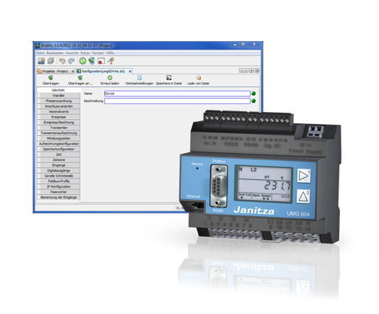
UMG 604
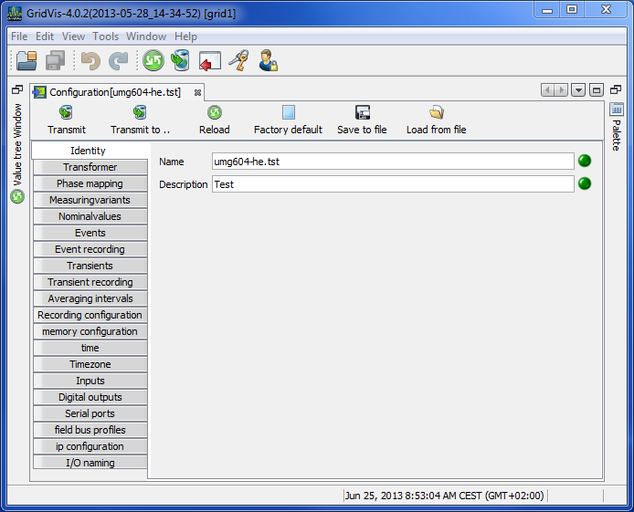
Identity
The name is used, among other things, to identify the device in the device list.
Additional information can be saved under Description.
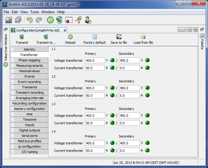
Transformers
Voltage transformers
The UMG 604's voltage measurement inputs are designed for the measurement of low voltages in which rated voltages (L-N/PE) of up to 300 V against earth can occur.
Voltage transformers are necessary in grids with higher rated voltages.
The converter requirements for each voltage input must be determined separately.
Current transformers
Currents up to 5 A can be measured directly. Observe the installation guide when doing this.
Transformers are used when measuring currents greater than 5 A.
Set the current converter requirements for the current measurement input.
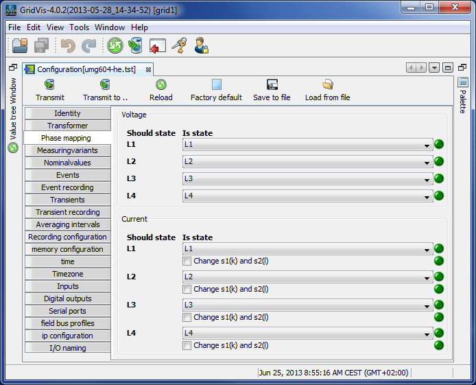
Phase mapping
The phase wiring and the electricity consumer wiring can be redefined by the phase assignments.
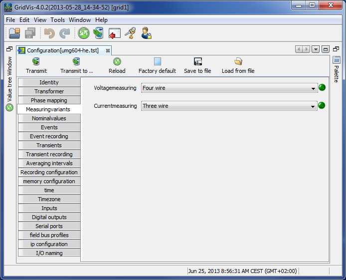
Measuring variants
Set the device's connection variant for the voltage and current measurements (manual).
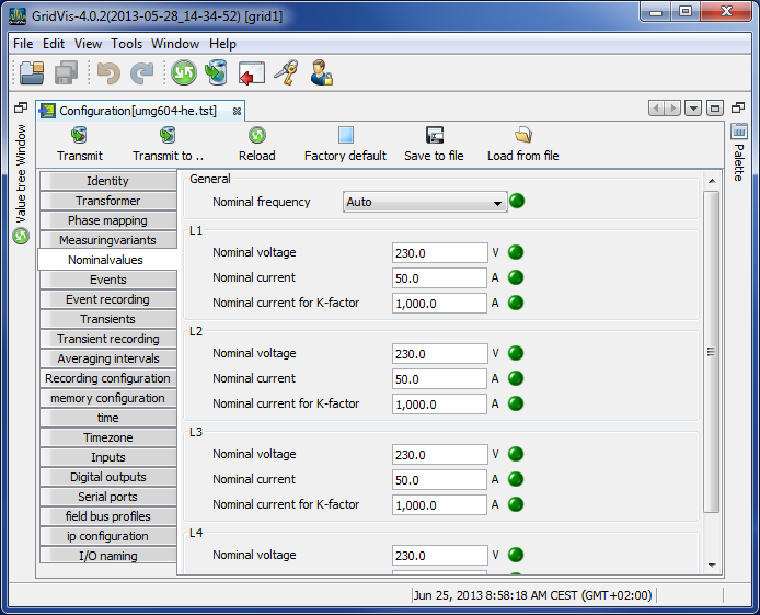
Nominal values
All 4 of the measurement channels are activated via the rated frequency. Select the mains frequency in accordance with the available grid supply.
Nominal values are required as a reference to identify events (overvoltage/undervoltage and overcurrent).
The rated current of the transformer at the supply is required in order to calculate the K factor.
The relevant voltage indicates whether a measurement is to be made between the
outer conductor L-L or between
outer conductor L and neutral conductor N.
The relevant voltage is required for the calculation of harmonics, events and flicker.
For UMG 508, UMG 604 and UMG 104 devices with the firmware small Rel. 2.x, the relevant voltage is not adjustable and is always L-N.
In the 3-conductor network (e.g. mean voltage) the relevant voltage relates to a calculated star point.
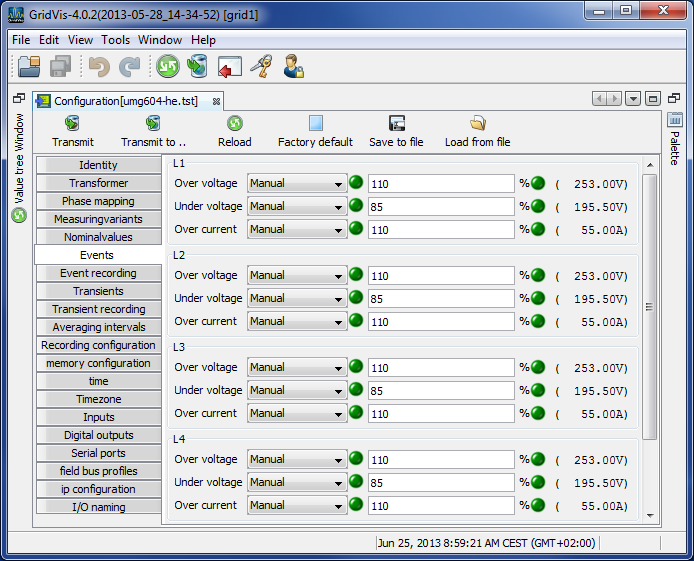
Events
An event occurs if threshold values set for the current and the voltage are violated.
An event has a mean value, a minimum or maximum value, a start time and an end time.
The GridVis® event browser can display recorded events.
Threshold values are set per measurement channel (L1 .. L4) for excess voltage, undervoltage and overcurrent as a percentage of the nominal values.
Threshold values can be switched off by switching the Manual/Off button to Off.
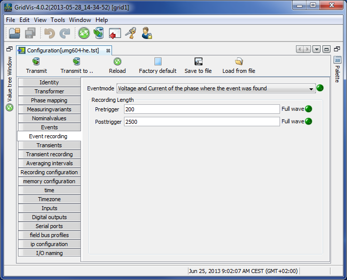
Event recording
Effective values recorded in the UMG 604 describe the trend of full wave effective values.
Effective value recording can be started by an event or by a JASIC program.
Various recording modes can be selected to record effective values triggered by an event.
Only the value in which the event was found.
Only voltage and current in the phase in which the event was found.
All of the inputs of the value in which the event was found.
All of the values in all the inputs
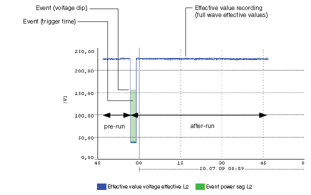
The length of the effective value record is determined by the number of full wave effective values up to the beginning of the event (pre-run) and by the number of full wave effective values after the beginning of the event (after-run).
Pre-run setting range: 64 .. 8192 full waves (up to firmware rel. 1.1: 64..6144 full waves)
After-run setting range: 64 .. 8192 full waves (up to firmware rel. 1.1: 64..6144 full waves)
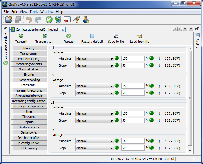
Transients
Transients are fast voltage changes.
The UMG 604 recognizes transients if they are longer than 50 µs, although it only monitors the four voltage measurement inputs.
There are two independent criteria by which transients are recognized.
Absolute: If a sampled value exceeds the set threshold, a transient is recognized.
Available settings:Off - transient monitoring has been switched off
Automatic - the threshold value is calculated automatically and comes to 150% of the current 200 ms effective value.
Manual - the transient monitoring uses the set threshold values.
Fast increase: If the difference between two neighboring sampled points exceeds the set threshold, a transient is recognized.
Available settings:Off - transient monitoring has been switched off.
Automatic - the threshold value is calculated automatically and comes to 12% the current 200 ms effective value.
Manual - the transient monitoring uses the set threshold values.
If a transient has been recognized, the threshold value increases by 20 V, both in automatic and in manual mode. This automatic increase of the threshold value switches off within 10 minutes.
If a transient has been recognized, the wave form will be saved to a transient record.
If a further transient is recognized within the next 60 seconds, it will be recorded with 512 points.
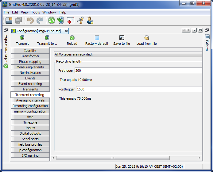
Transient recording
Transient recording
If a transient has occurred, the wave shape can be saved in a transient record with an adjustable number of sampled points before and after the transient.
The time between two sample points is always 50 µs.
You can choose between the following measurement channels for recording in the transient record:
The phase voltage will be recorded with the transient.
The phase voltage and current will be recorded with the transient.
All currents will be recorded.
All voltages and all currents will be recorded.
Recording length
The number of sample points to be saved before the transient occurred:
Pre-run setting range: 64 .. 8192 points (up to firmware rel. 1.1: 64..6144 points)
After-run setting range: 64 .. 8192 points (up to firmware rel. 1.1: 64..6144 points)
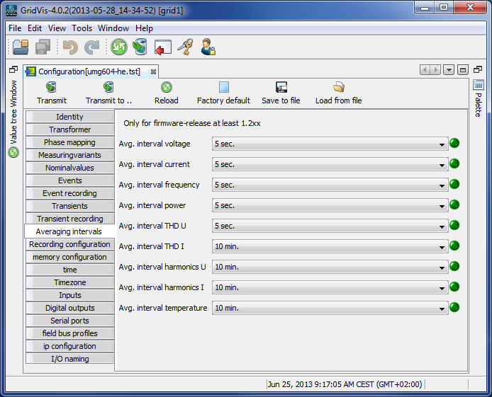
Averaging intervals
Parameterization of the floating average (previous name for trailing value indicator) for the individual measurement values.
The measurement values of the mean values are marked in the device display with an overline.
The values can also be used for operators or comparators (JASIC).
The adjustment range of the reporting times of the selected group (L1-L4) is 10, 15, 30, 60 seconds and 5, 8, 10, 15 minutes.
The settings of different reporting intervals for each individual phase are made on the device.
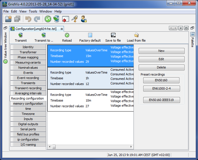
Recording configuration
Recording configuration
Up to 16 records can be configured when configuring recording.
A record can have a maximum of 1000 values.
A record holds a measurement value or the mean value of the measurement value.
Mean value records can also include the minimum and the maximum values.
Mean values, minimum values and maximum values are derived from the measurement values in the measurement timeframe.
The mean value measurement time frame is established by the time set under Timebase.
Measurement values are saved once the time set under Timebase has run its course.
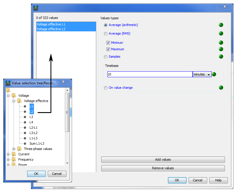
Setting up / editing a recording configuration
An individual recording instance can be set up using the New or Edit buttons.
Measurement values are selected in the recording window using the Add values button.
To do so drag the desired measurement value (measurement value group) over the value field. The measurement values are adopted and displayed.
The selected measurement values can be described in more detail via the option Mean (arithmetical), Mean (RMS), Minimum, Maximum, Sample and With value change.Mean (arithmetical)
The arithmetical mean is the ratio of the sum and the number of all 200ms measurement values:
x (arithm.) = (x1+x2+x3...) / nMean (rms)
This value describes a quadratic mean (potential mean) with:
x (rms) = root ((x12+x22+x32+..) / n)Minimum / Maximum
When these buttons are selected, the means of the minimum and/or maximum values are recorded.Sample
Sample describes the recording of the measurement value within the defined time duration. The time baseline defines the time intervals at which the recording is made.With value change
If the measurement value is changed, the 200 ms measurement value is recorded. This setting is useful for, for example, the monitoring of digital inputs and outputs (not with high frequency signals) or of the temperature input.
In contrast to the arithmetical mean, the quadratic mean is of increasing importance when the measurement values vary greatly cyclically. Outliers in the measurement values thus have a greater significance. With a value like voltage, it is a good idea to take this more into account than for a power value.
Using the Delete values button, selected measurement values can be deleted.
EN50160 and EN61000-2-4 presettings selection aid
Via the EN50160 and EN61000-2-4 buttons, recording configurations can be predefined.
If the device does not support measurement as per EN50160, a prompt appears.
Calculation of the required memory capacity
With the default programming for recordings a data memory of approx. 11 MByte p.a. will be occupied.
Recording 1
23 values, 900 seconds
(4+4+4) * 23 + 24 = 300 Bytes per dataset
A dataset is written into the memory every 900 seconds.
This means that the required annual memory capacity is
=>96 datasets per day, => 35040 datasets p.a., => 10.512 MByte p.a.
Recording 2
12 values, 3600 seconds
4 * 12 + 24 = 72 Bytes per dataset
A dataset is written into the memory once an hour.
This means that the required annual memory capacity is
=>24 datasets per day, => 8760 datasets p.a., => 630.72 kByte p.a.
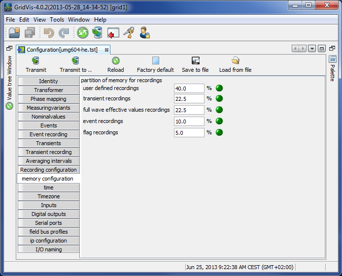
Memory configuration
The UMG 604 has a storage capacity of approx. 112 MByte.
The data memory has been partitioned as follows ex works:
40% for user-defined recording.
22.5% for the recording of transients.
22.5% for the recording of full wave effective values.
10% for the recording of events.
5% for the recording of flags (flagging).
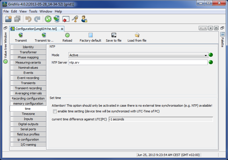
Time
Configuring of time
The UMG 604 has a clock with a battery backup. The fault in the clock's quartz is aligned with room temperature during production so that the clock only deviates by ± 1 minute/month. If transient records and event records are to be compared with other measurement records, it is recommended that the time indicated by the UMG 604 be compared and aligned with that in a time server. For this purpose, the UMG 604 requires the Ethernet interface (option). The network time protocol (NTP) is used for synchronization.
Mode
Off - synchronization of the clock with an external time server is switched off.
Lists - The UMG 604 is waiting for time information from a time server.
Active - The UMG 604 automatically requests time information from an NTP server every 64 seconds.NTP server - this is where the time server's address is input.
Time setting
During configuration, the clock can be aligned to UTC time in the connected PC.
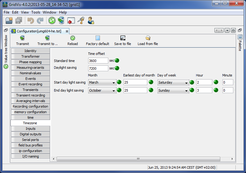
Time zone
All time information with regard to measurement values, events and transients relate to UTC time (Coordinated Universal Time). The GridVis® converts UTC time to Central European Time (CET) when it displays measurement results. Central European Time (CET) is the applicable time zone in central Europe and therefore also in Germany.
Winter time - time offset from Central European Winter Time relative to UTC time.
Summer time - time offset from Central European Summer Time relative to UTC time.
Start of daylight saving time - start of daylight saving time.
End of daylight saving time - end of daylight saving time.
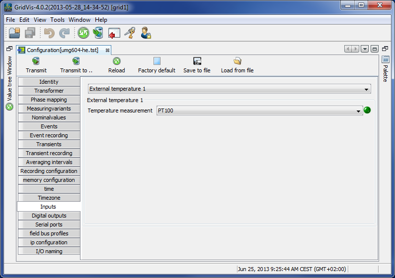
Inputs
The UMG 604 has two digital outputs and an input used to measure temperature. Both digital inputs can be used as digital inputs and as input pulse meters.
A pulse value can be assigned to every pulse input.
Various temperature sensors can be connected to the input used to measure temperature:
PT100 - temperature range −55 °C .. +175 °C
PT1000 - temperature range −40 °C .. +300 °C
KTY83 - temperature range −99 °C .. +500 °C
KTY84 - temperature range −99 °C .. +500 °C
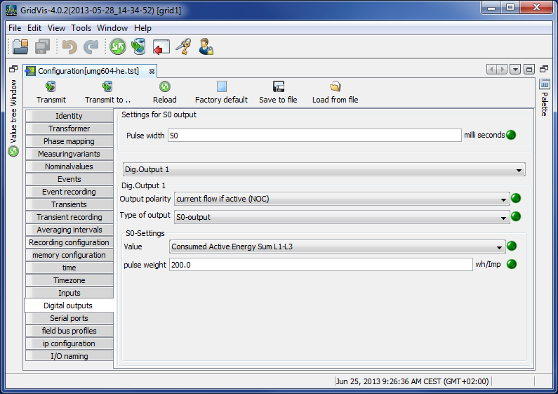
Digital outputs
The UMG 604 has two digital outputs. Both of these digital outputs can be programmed for event messages or as a pulse output (S0 output).
Each digital output can be programmed as a NC or NO contact.
One or more events can be allocated to an output if it is programmed for event updates.
The event output activates if a selected event occurs.
Serial outputs
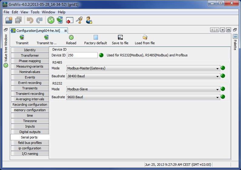
Device ID
The device ID (device address) is required for Modbus communication and for the Profibus.RS485
Setting the Modbus selection between Modbus master, Modbus slave, transparent gateway and BACnet IP.
Baud rate selection from 9600 bps, 19200 bps, 38400 bps, 76800 bps, 115200 bps and 921600 bpsRS232
Setting the Modbus selection between Modbus slave, debug protocol and SLIP
Baudrate selection of 9600 bps, 19200 bps, 38400 bps, 57600 bps, 76800 bps, 115200 bpsProfibus (option)
Note! Additional Profibus settings are made under Fieldbus profiles.
Fieldbus profiles
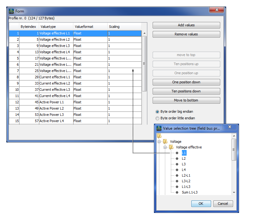
Fieldbus profiles hold a list of values which can be read or written by a PLC via the Profibus.
Using the GridVis®, 16 fieldbus profiles can be configured.
In the UMG 604, with firmware from 1.095, 4 fieldbus profiles are preconfigured ex works.
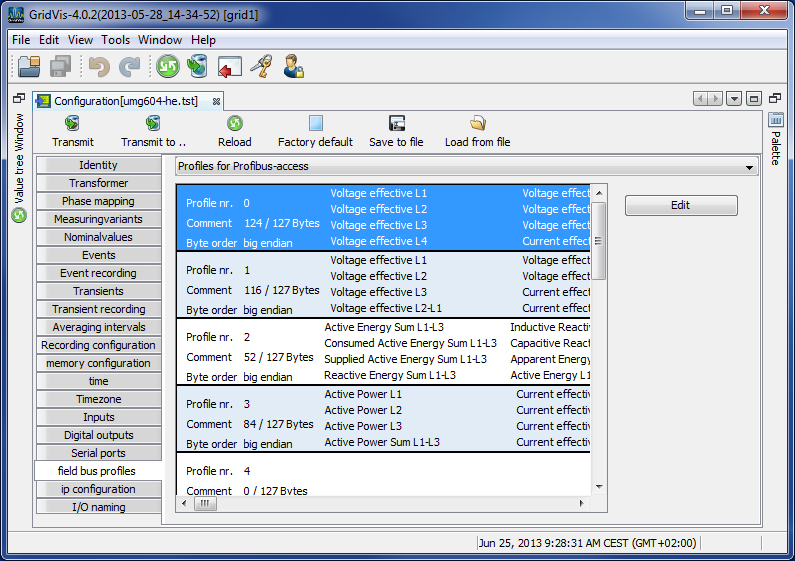
Using the Edit button, the preconfigured fieldbus profiles can be retrospectively changed.
Clicking the Add values button opens an selection of measurement values or measurement value groups.
Drag the desired measurement value (measurement value group) over the value field. This saves and displays the measurement values.Using the Delete values button, selected measurement values can be deleted.
The measurement value sequence can be determined with the position buttons.
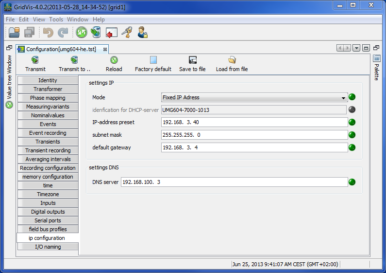
IP configuration
For devices with the Ethernet option, it is necessary to set at least the IP address and the subnet mask.
In the UMG 604, it is possible to choose between the options fixed IP address, BootP and DHCP mode.
Fixed IP address
All settings are undertaken by the user.BootP
BootP allows for the fully automatic integration of a UMG 604 into an existing network.DHCP mode
When started, the UMG 604 pulls all of its settings from the DHCP server.
Important: Any settings should only be made after these have been discussed with the administrator.
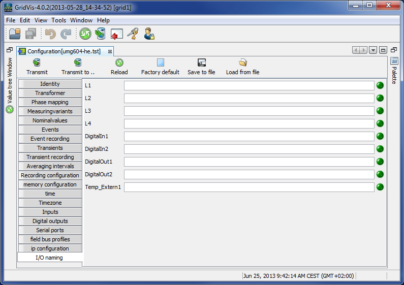
Naming of inputs and outputs
Enables naming of inputs and outputs.
The respective inputs and outputs can be assigned names by entering a name in the corresponding box.