Measurement
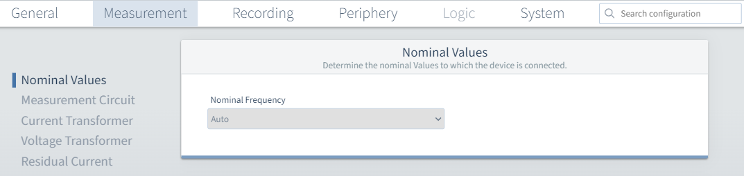
Nominal values
Nominal frequency: The nominal frequency is determined automatically.
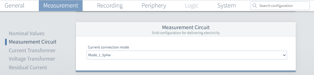
Mains
Current channel mode: Set the connection variant here. The following variants are possible:
Four-wire
Three-wire
Single-wire
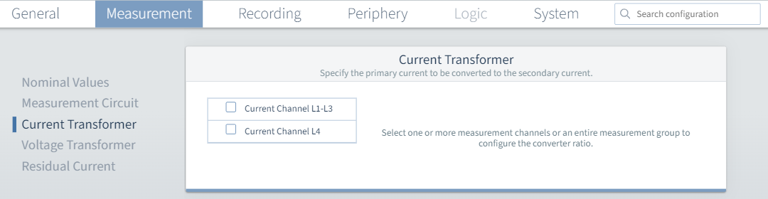
Current transformer
Current channel L1-L3: Set the ratio of your current transformers for phases L1 to L3.
Current channel L4: Set the ratio of your current transformers for phase L4.
In the upper area you can give current channel L4 a user-defined name. To do this, you can either click directly on the 4th current measurement input in the diagram or select the check mark for Current channel L4.
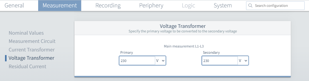
Voltage transformer
Main measurement L1-L3: Set the ratio of your voltage transformers for phases L1 to L3.
A voltage ratio of 400 V primary to 400 V secondary means that phases L1-L3 are directly connected.
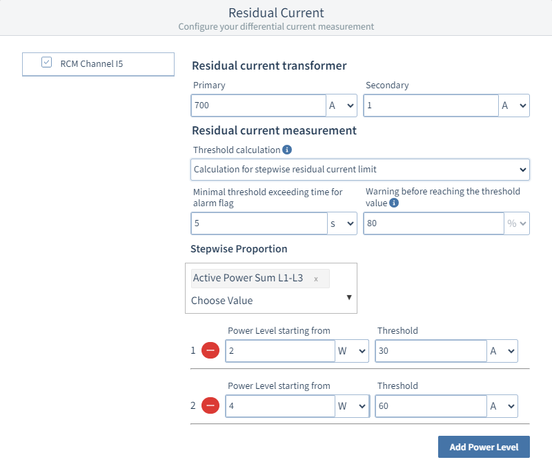
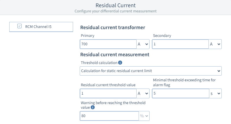
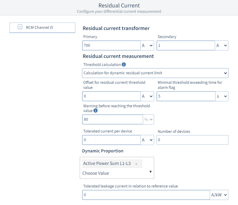
Residual current
Residual current transformer : Set the ratio of your residual current transformer .
Residual current detection: You can either switch off the residual current measurement or choose between three variants:

Static limit value calculation: With static residual current limit, you can enter a fixed residual current in amperes or milliamperes. You can also enter a time in seconds or milliseconds that the residual current must be present before the limit violation is output. This is the minimum exceedance time for the alarm flag.
This limit value can be used to set a warning in percent, which is the warning before the limit value is reached.
For example, if you have set a limit value of 10 A and a warning of 80%, the warning will be triggered at 8 A.
Dynamic limit value calculation: The Warning and the Exceedance time behave in the same way as for the Static limit value calculation.
You can select a reference value under Dynamic portion. The unit of the leakage current to be tolerated in relation to the reference value is set automatically based on this selection.
The tolerated leakage current must be entered next to this. Together with the offset for residual current limit, the residual current per consumer and the number of consumers, the following calculation results:
Dynamic limit value =
Offset for residual current limit value +
( Residual current per consumer x Number of consumers ) +
( Tolerated leakage current with respect to reference value x Reference value )
Stepwise limit value calculation: The Warning and Exceedance time behave in the same way as in the static limit value calculation and refer to all levels of the table to be created below.
Add power level
Use this button to add a power level for calculating the stepwise limit value. A maximum of ten power levels can be defined. Power levels can be removed via the
button.
Power level from
Enter the reference value from which the power level becomes active. Observe the following: Each additional power level must be selected larger than the preceding power level.Limit value
Enter the limit value valid for the power level.