Power quality*
Set the power quality limit values here. If these limits are exceeded or undershot, the measurement device evaluates this as an event and starts a recording including a lead time of 20 s and a lag time of 20 s before and after the trigger time.
If the limit violation lasts longer than 20 s, a separate event recording is started for the end time.
The data are recorded in the measurement device itself. However, due to the display size, only a sequence section of 2.5 s before and after the trigger time is shown in the measurement device display. Consequently, recorded events can be better analyzed in the EventBrowser of the GridVis software.
Settings
Note
* This configuration card is only available with measurement devices of the PQ-L series.
** This setting is only available for measurement devices with Class S (as of firmware 3.42).
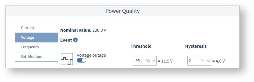
Power quality (general settings)
Nominal value
The nominal values shown are taken from the Nominal values configuration card or the settings in the device.
Limit value
Event recording starts when this limit value is exceeded or undershot. The hysteresis is not relevant for the start time of the limit violation.
Hysteresis
Use hysteresis if the event is to end only after a time delay, although the cause (trigger) is already no longer present.
In the event of a limit value being exceeded – for example in the event of overcurrent or overvoltage – the following applies:
Without hysteresis, an event ends as soon as the measured value is once again below the limit value.
With hysteresis, the event ends only when the measured value falls below the limit value by the value of the hysteresis.
Example image: UMG 96-PQ-L
Current
Overcurrent L1..L3, overcurrent L4
If event recording is to be started when there is overcurrent, activate the slide switch and define the limit value and hysteresis.
Overcurrent L5, Overcurrent L6
Before defining the power quality settings, make sure that the measuring mode of the multifunction channels is already set correctly. To set or check, click on a multifunction channel in the device image.
If the measuring mode of the multifunction channels is DC power, channel 6 is used for voltage measurement (see the voltage transformer configuration card). The limit value for Overcurrent L6 therefore refers to the DC voltage that corresponds to the measured current of 0-20 mA.
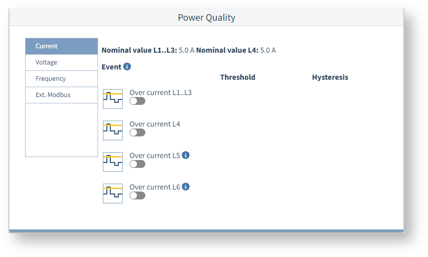
Example image: UMG 96-PQ-L
Voltage
Undervoltage, overvoltage, voltage interruption
If event recording is to be started in these cases, activate the slide switch and define the limit value and hysteresis.
Rapid voltage change **
When these slide switches are on, the measurement device starts recordings if there are voltage dips, voltage swells or voltage interruptions according to EN 61000-4-30. Only available if Class S is activated.
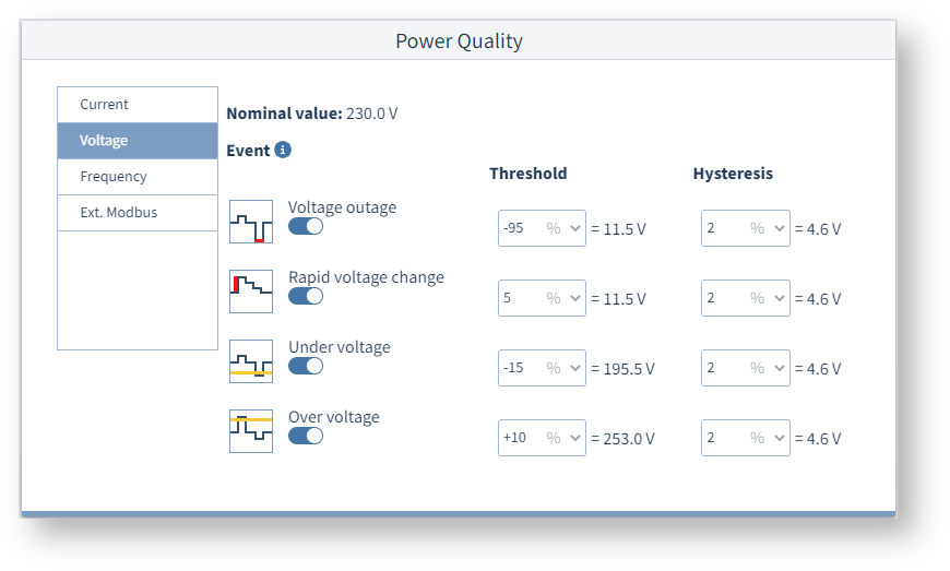
Example image: UMG 96-PQ-L (Class S)
Frequency **
Overfrequency **, Underfrequency **
Frequency variations can cause damage to sensitive equipment (e.g. motors) and additional heat loss.
Turn on the slide switches to record frequency events like these.
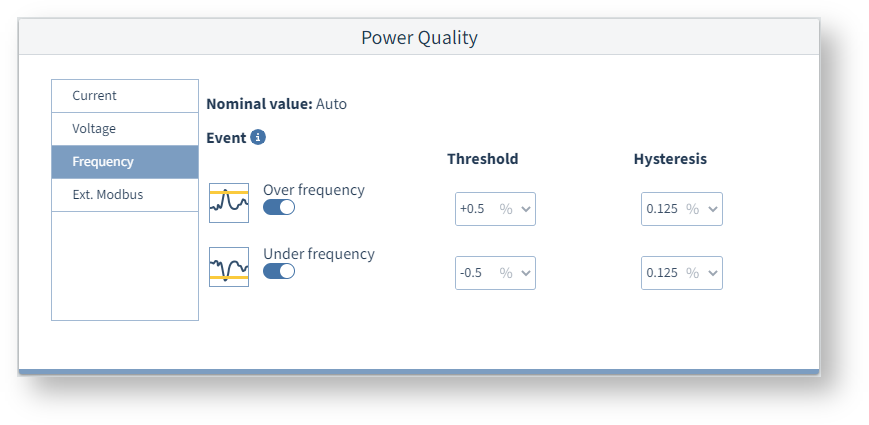
Example image: UMG 96-PQ-L (Class S)
Ext. Modbus
Start event recording
You can manually start event recording by pressing this button. A corresponding signal is sent to the measurement device via Modbus RTU.
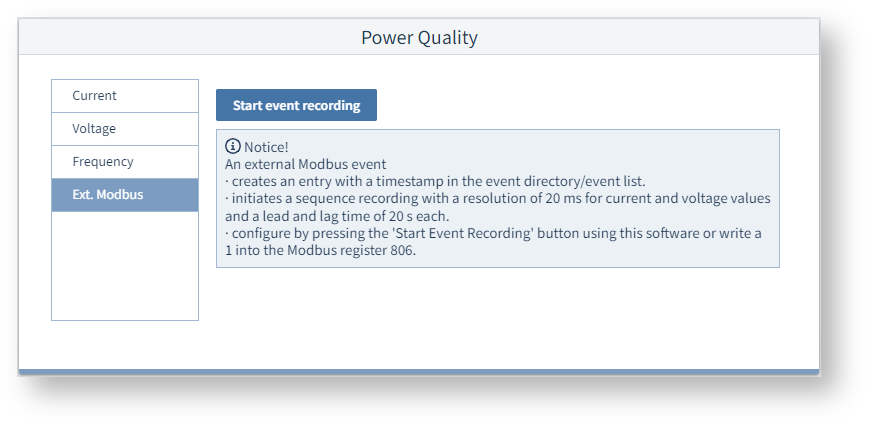
Example image: UMG 96-PQ-L