Residual current*
You can measure residual currents with the multifunction channels L5 and L6 of the 96-PA-RCM-EL module. The module measures the residual currents L5 and L6 in the set measuring mode (AC / DC) and sends them to the basic device. As with the basic device, the measuring interval is 200 ms. The RMS values and the harmonics up to the 40th are measured.
Note
* This configuration card is available only if the measurement device is equipped with the 96-PA-RCM-EL module for residual current measurement.
How to configure residual current measurement:
Click the connection of a multifunction channel L5 or L6 in the device image
 .
.Select either RCM 0..20 mA, RCM 4..20 mA or Mode AC as the measuring mode.
The Residual current configuration card now shows the necessary parameters.
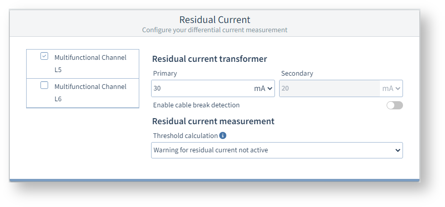
Select the checkbox Multifunction channel L5 or Multifunction channel L6 and set the parameters described below.
Settings
Multifunction channels L5 and L6
The Measuring mode defines which signal type is applied to the channel.
The following settings can be made in the measuring mode:
AC mode: Use this mode for passive residual current transformers with a ratio (e.g. 700:1) that provide an AC signal (0-30 mA ACRMS).
RCM (0-20 or 4-20 mA): Use this mode for active residual current transformers that, for example, output a DC signal of 20 mA at a 10 A current flow. Type B and B+ residual currents can be detected using appropriate active transformers. However, this does not provide any information about the harmonic currents of the residual currents.
Whether 0..20 mA or 4..20 mA depends on the respective transformer (set according to transformer rating plate).
DC power (0-20 or 4-20 mA): Use this mode if you want to measure a DC current via channel L5 and a DC voltage via channel L6.
When DC power is selected, the Residual current configuration card is hidden. Make the settings on the configuration cards Current transformer (L5) and Voltage transformer (L6).
Note: This means AC mode has no relation to "Type AC" residual current devices, but instead is referenced to the signal form at the input.
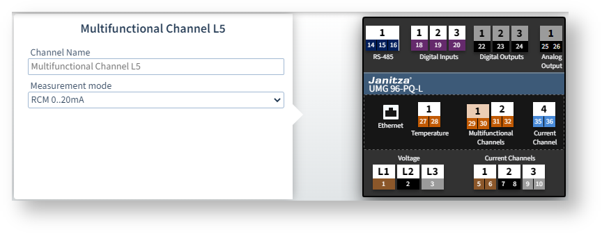
Example image: UMG 96-PQ-L
Measuring mode = AC mode or RCM
The following settings are available in these measuring modes on the Residual current configuration card:
Residual current transformer
Set the primary current of the current transformer.
Switch on cable break detection
In the event of a cable break, an alarm is output on the display and via Modbus (CT connection break). You can also switch on cable break detection on the device under Configuration > Measurement > Residual current.
Limit value calculation
The measurement device can work with different methods of limit values. When you move the mouse over the Info icon, a tooltip shows a description of the different methods of limit value calculation.
Fill in the additionally displayed fields depending on the selected method of limit value calculation (e.g. dynamic).
Static and dynamic limit value calculation
If a method of limit value calculation is active, a warning or alarm is shown on the device display when the limit value is exceeded. The warning levels are:
Warning (for static or dynamic calculation): If the value set in Warning before reaching limit value is exceeded, a warning is triggered and the Modbus register for the RCM status is updated.
Warning2 (for static or dynamic calculation): If the set limit value is exceeded for a shorter time than the Minimum overrun time for alarm flag, only the RCM status register is updated (no further action).
Alarm: If the set limit value is exceeded for at least the duration of the Minimum overrun time for alarm flag, an alarm is triggered.
Warnings or alarms can only be confirmed or cleared on the device. RCM1 corresponds to multifunction channel L5 and RCM2 to multifunction channel L6.
GridVis queries the RCM status registers approximately every 200 ms to obtain the current RCM events. The RCM status can also be read out via Modbus in individual bits (e.g. whether a warning or alarm is currently pending or was pending in the past).
Stepwise limit value setting
Use this method of limit value calculation if you want to allow higher residual current limit values when the active power is higher. To do this, you must fill in a table of power levels and corresponding residual current limit values. The table does not have to be sorted, but sorting makes it easier to understand.
Example image: UMG 96-PQ-L
Measuring mode = DC power
If you have selected this measuring mode, both channels L5 and L6 must be set to the same value.
Make the settings on the configuration cards Current transformer (L5) and Voltage transformer (L6).
The Residual current configuration card is hidden in this measuring mode.