Digital input
Define the function for each digital input.
Settings
How to configure a digital input:
Click on the input in the device image.
If desired, assign a Channel name to the input. The channel name is stored in the database.
Select the Mode.
The Digital input configuration card is adapted to the selected mode.Make the settings on the configuration card.
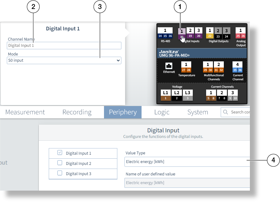
Example image: UMG 96-PA-MID+
The settings available on the configuration card depend on the value in the Mode field.
Not every mode is available for every digital input (see the user manual).
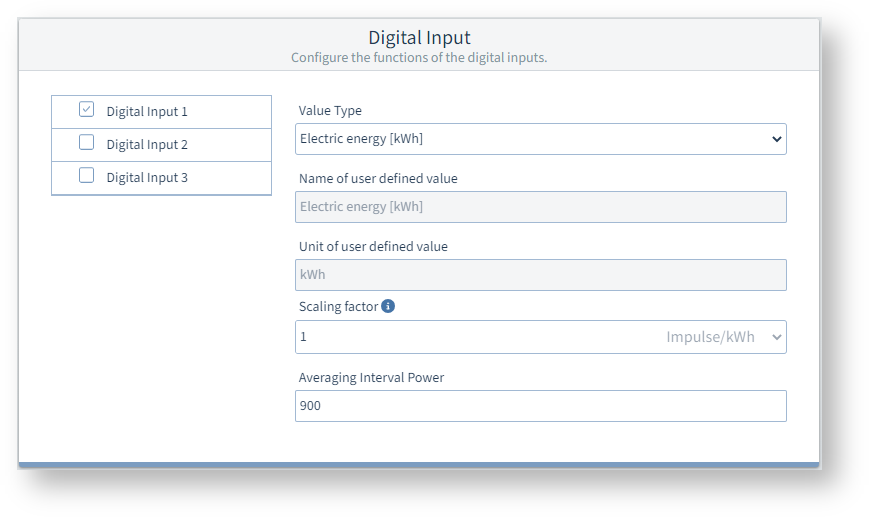
Mode = S0 input
The input operates as a pulse counter.
Value type
Select a value. If the drop-down list does not contain the value type or unit, select User defined.
Scaling factor
Enter the scaling factor as the reciprocal of the pulse valency (see user manual).
Averaging time
A setting of 900 (seconds) corresponds to 15 minutes. The incoming pulses are counted over this duration and an average value is calculated.
Example image: UMG 96-PQ-L
Mode = Tariff control input
The measurement device has internal counters for two tariffs each (tariffs 1 and 2). The input can be used to switch between the HT and LT tariff settings.
No setting is required or possible on the Digital input configuration card.
Mode = Synchronization of the device clock
For this type of synchronization, connect a time pulse generator to digital input 2, e.g. the electric utility pulse or a GPS timer
(GPS radio receiver, for receiving and processing the GPS time signal; available as a Janitza accessory).
No setting is required or possible on the Digital input configuration card.
Mode = Drag indicator synchronization
Make the further settings under General > Drag indicator (see user manual).
No setting is required or possible on the Digital input configuration card.
Mode = External event recording
External signal transmitters can be connected via the digital input to detect events such as voltage drops. The time stamp of the detected signal is automatically logged in the event list.
The trigger for the event can be either the rising, falling, or changing edge of the input signal.
No setting is required or possible on the Digital input configuration card.
For more information on event recording via the digital inputs, refer to the user manual.