Residual Current
How do I configure my device for a residual current measurement?
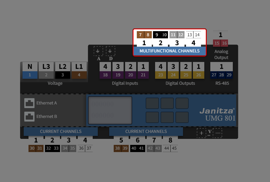
Step 1: Select multifunction channel
The measurement device is suitable as a residual current monitoring device (RCM) for monitoring alternating currents, pulsating direct currents and direct currents.
The multifunction channels provide the corresponding measuring mode for this purpose. Each multifunction channel can be used for residual current measurement.
First, in the device overview, select the higher-level measurement group Multifunction channels.
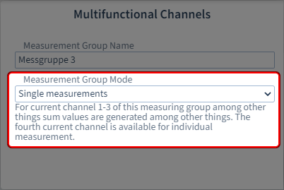
Step 2: Measurement group mode → Single measurement
In order for the setting option for residual current measurement to appear for channels 1 - 3 under Measuring mode, the measurement group mode Single measurement must be set for the entire measurement group.
Note
The measurement group modes have an influence on the setting options of the individual current and multifunction channels.
What are measurement group modes? See Measurement group mode .
What settings can I make via the interactive area?
Step 1: Assign channel name
Now select the individual multifunction channel for configuration in the device overview.
Assign a name or designation for identification.
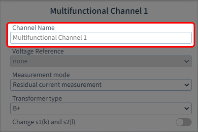
Step 2: Specify the measuring mode
The following measuring modes are available:
Current measurement
Temperature measurement
Residual current detection
Since you want to use residual current measurement, select: Residual current measurement.
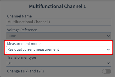
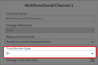
Step 3: Select the current transformer type (A or B+)
With selection of residual current measurement, another parameter appears.
The following current transformer types are available:
A (sensitive to pulsed current)
Sinusoidal alternating residual currents and pulsating direct residual currents
B+ (universally current sensitive)
Additional smooth / sinusoidal DC residual currents and high frequency residual currents (<20 kHz)
Special features
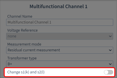
Swap s1(k) and s2(l)
If the current transformer connections were connected incorrectly during installation, you can swap the connection polarity via the device configurator.
How do I configure the residual current measurement?
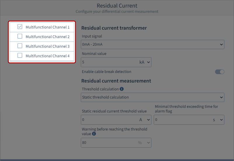
Step 1: Select multifunction channel
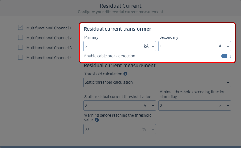
Step 2 (Option 1): Configure residual current transformer (current transformer type A)
Primary
Enter the primary current of the current transformer and the appropriate unit in the input field.
Secondary
Enter the secondary current of the current transformer and the appropriate unit in the input field.
Enable cable break detection
Activate the sliding switch so that the device monitors the connection to the residual current transformer.
The cable break detection only works with passive current transformers (AC) and current transformers with a 4-20 mA secondary output.
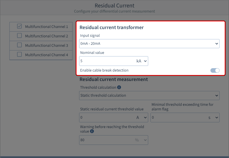
Step 2 (Option 2): Configure residual current transformer (current transformer type B+)
Input signal
Specify the range of the input signal: 0 … 20 mA or 4 … 20 mA
Nominal value
Enter the rated current for the channel in the input field and select the appropriate unit.
Enable cable break detection
Activate the sliding switch so that the device monitors the connection to the residual current transformer.
The cable break detection only works with passive current transformers (AC) and current transformers with a 4-20 mA secondary output.
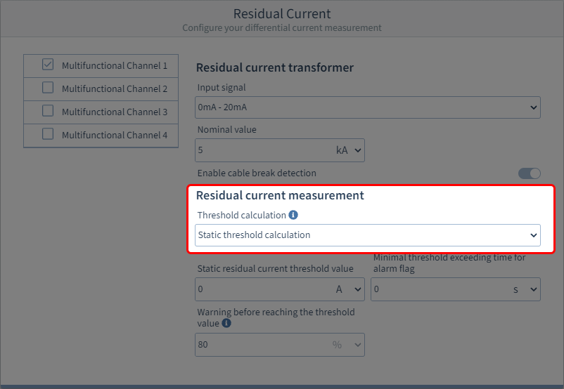
Step 3: Configure type of threshold calculation
Static
A constant threshold is defined. If this threshold is exceeded, a threshold violation occurs.
Dynamic
In dependence on a reference value, the threshold for violations changes continuously and with it the respective warning. The respective threshold is calculated from the reference value, multiplied by a scaling factor, plus a static offset.
Step by step
Depending on the power level (reference value), the threshold offset for violations changes step by step. Different threshold offsets can be defined for up to 10 power levels. The respective thresholds are calculated from the static residual current threshold , plus the threshold offset.
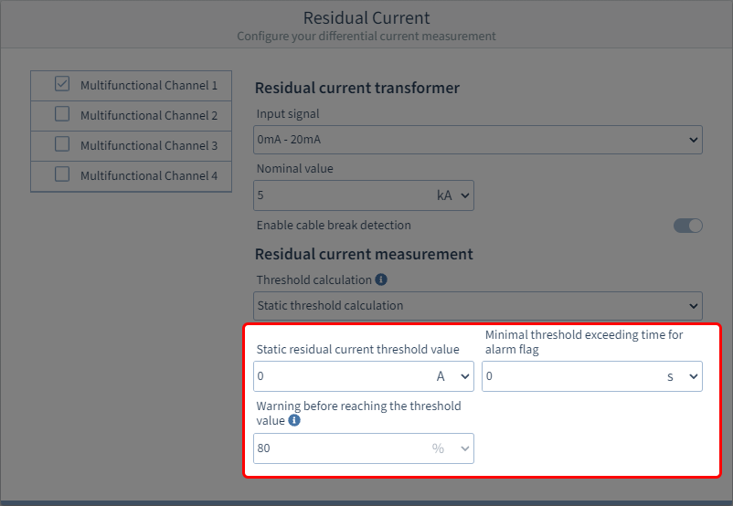
Step 4: Basic settings for the threshold calculation
Static residual current threshold value
Here, enter the static residual current threshold of your residual current measurement in the appropriate unit.
Minimal threshold exceeding time for alarm flag
Enter an exceedance time. If the measured residual current exceeds the residual current threshold for longer than this exceedance time, the alarm flag is set in the device.
Warning before reaching the threshold value
Enter a warning level in percent. If a measured residual current exceeds this percentage value of the threshold , the warning flag is set in the device.
Step 5 (Option 1): Settings for dynamic threshold calculation (dynamic portion)
Select a reference value:
Segment
Select the component from which the reference value originates:
Basic device
Module 1
Module 2
…
Measurement group
Select the measurement group of the reference value.
Measured value
Select the type of the measured value.
Phase / Channel
Select the channel whose measured value is to be used.
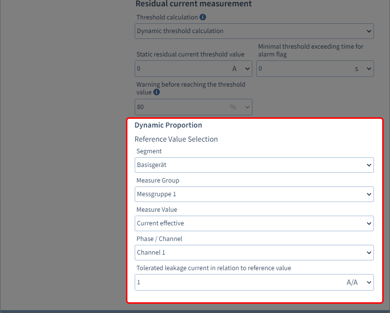
Tolerable leakage current (scaling factor) in relation to reference value
Enter the tolerable leakage current for calculating the dynamic threshold (threshold value portion in relation to the reference value). Select the appropriate unit.
Calculation of the dynamic threshold:
Dyn. threshold= reference value x scaling factor + stat. offset
Step 5 (Option 2): Settings for stepwise threshold calculation (stepwise portion)
Select a reference value:
Segment
Select the component from which the reference value originates:
Basic device
Module 1
Module 2
…
Measure Group
Select the measurement group of the reference value.
Measure Value
Select the type of the measured value.
Phase / Channel
Select the channel whose measured value is to be used.
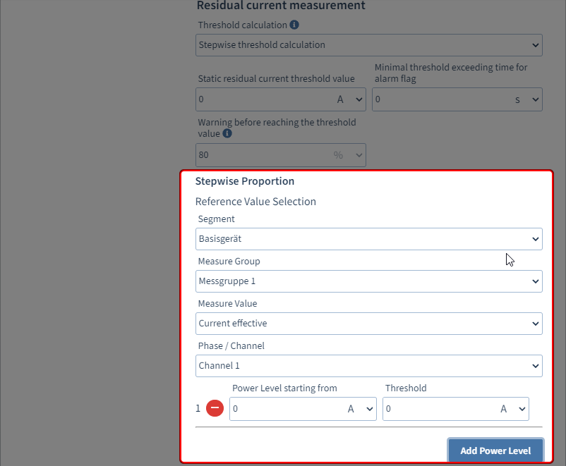
Add Power Level
Use this button to add a power level for calculating the stepwise threshold . A maximum of ten power levels can be defined. Power levels can be removed via the button. If no power level is configured, the static residual current threshold applies.
Power level starting from
Enter the reference value from which the power level becomes active. Note: Each additional power level must be selected larger than the preceding power level.Threshold
Enter the threshold offset valid for the power level.
Calculation of the stepwise threshold:
Stepwise threshold = stat. threshold + threshold offset